The Fascinating Story Of The USAF’s “Upside-Down Air Force”美国空军“颠倒空军”的迷人故事
From fighters to tankers, the Upside-Down Air Force has tested numerous inverted aircraft since the early 1970s.
Published May 31, 2024 6:37 PM EDT
Back in the 1970s, as USAF aircraft featured increasingly sophisticated communications and electronic warfare systems, the service established a secretive testing project to measure the emissions and effectiveness of aircraft antennae systems. Known unofficially as the “Upside-Down Air Force,” the project is still an important part of USAF testing to this day.
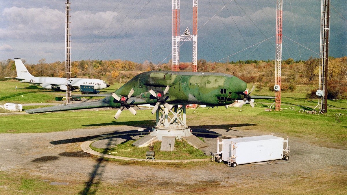
The Upside-Down Air Force has involved many types of aircraft over the years, from fighters to tankers, including the C-130 Hercules featured above, which was pictured in July 1986. At that time, the testing operation was part of the Air Force’s Rome Air Development Center (RADC), attached to the then Griffiss Air Force Base located in Rome, New York.
The project involves bolting aircraft to 30-to-50-foot high pedestals. Essentially, this allows the Air Force to perform aircraft underside antenna functionality and emissions tests on the ground, rather than in the air. The latter is both very costly and less capable of delivering detailed data. Doing this work on the ground provides far more control over the positioning of aircraft compared to during flight testing and longer periods can be set aside to test than just when an aircraft is available and airborne. Mapping emissions patters around the aircraft and finding out things like what parts of the jet interfere with signals from different aspects were all part of this kind of testing.
An YA-10 Thunderbolt II aircraft is mounted on a pedestal during a test at the Rome Air Development Center’s Newport Test Site, July 1984. National Archives National Archives
The RADC was inaugurated at Griffiss on June 12, 1951, and was created to lead the development of early warning and command and control equipment for continental air defense under Air Force Systems Command (AFSC). It was not until 1971 however that the Upside-Down Air Force was established by RADC. Three research sites were created for testing under the project around Griffiss; all of which were selected because of the relative isolation of the land and its topography.
At the Verona test site, located roughly 11 miles southwest of the base, the Precision Antenna Measurement System (PAMS) was used from the early 1970s to perform dynamic antenna measurements and evaluate the radiation characteristics of airborne aircraft. This allowed for various sorts of data on the effectiveness of antennas to be collected. Prior to this, antennas would be tested on partial aircraft mockups or scale models. However, as the Air Force noted , “this method has not provided enough realistic data on the antennas and the effect of the aircraft on the antenna characteristics. The development of the Precision Antenna Measurement System (PAMS) was undertaken to provide the type of data that is needed to accurately describe the effective radiation profile of airborne antenna systems.”
Verona Test Annex, New York, date unknown. U.S. Air Force
According to RADC’s 1973 guide on PAMS, the system provided “the capability to conduct engineering evaluations of airborne antennas designed for use on tactical aircraft equipped with ECM [electronic countermeasures] and associated penetration aids. The facility operates over the frequency range of 0.1 – 18 GHz and is capable of receiving AM, FM, CW or pulse-type signals of any polarization. Measurements are correlated with the aircraft altitude and are conducted on a real-time radiated basis. Types of measurements include power (peak signal amplitude), density (peak signal amplitude X the IF Bandwidth) and integrated (integrated amplitude over octave or increments of an octave bandwidth in terms of DBW/MHZ). The final plotted data can be outputed in polarization, rectangular or three dimension.”
For static testing, on the other hand, aircraft were separated by size. At the Newport test facility, located approximately 18 miles from Griffiss and consisting of several ranges, smaller aircraft testing was conducted, notably involving fighters and attack aircraft. From as early as 1972, RADC initiated efforts to investigate antenna measurement patterns of an ECM pod-equipped F-4 aircraft, for example.
An F-4 Phantom II aircraft shows one angle of its weapon configuration while atop a pedestal at the Rome Air Development Center’s Newport test site, May 1984. The aircraft’s antennas are being evaluated during the test. National Archives
“Originally slated for the salvage heap, RADC mounted the aircraft upside-down on a three axis pedestal at the… Newport Test Site to conduct the tests,” a subsequent official report by the Air Force states . “Antenna coverage by the pod appeared satisfactory with the pod removed from the aircraft, but unacceptable when installed.”
An F-111, F-15, and YF-16 were added in 1976, 1979, and 1980, respectively. Newport also received a YA-10 with the serial number 71-1369 , although when that occurred exactly remains unclear.
A right side view of an F-15C Eagle aircraft mounted upside-down on a pedestal at the Rome Air Development Center’s Newport test site, October 1988. A radar warning system pod mounted on the fuselage is being evaluated in comparison with the aircraft’s onboard radar warning system. National Archives
An A-10 Thunderbolt II aircraft is mounted on a pedestal during a test at the Rome Air Development Center’s Newport Test Site, July 1984. Cluster bombs and an electronics countermeasures pod are mounted on the aircraft’s pylons. National Archives
The Stockbridge research site, located 16 miles southwest of Griffiss, was reserved for static testing with larger aircraft. A B-52 was acquired in 1974, and in 1986 the aforementioned C-130 Hercules arrived at the base.
A view of an upside-down B-52 Stratofortness aircraft mounted on a pedestal at the Rome Air Development Center Stockbridge site, September 1979. Antennas around the B-52 are part of a new antenna measurement test facility. The new system allows engineers to determine the effectiveness of aircraft antennas without a test flight. National Archives
Positioning aircraft upside-down for antenna testing had distinct benefits for the Air Force. As Richard Rabe, whose career was spent mainly studying the effects of electromagnetic energy on antenna capability at the RADC’s Electromagnetic Compatibility Analysis Facility (EMCAF) noted previously , placing aircraft upright on pedestals would ruin tests due to the pedestals themselves getting in the way.
“The way to solve that problem was totally placing the aircraft upside-down. With antennae on the belly of the plane and the belly facing the sky, we could rotate, tip and spin the plane any way we wanted and the pedestal would be safely below the aircraft and out of the way.”
An F-4 Phantom II aircraft is removed from a 30-foot-high test pedestal prior to being turned over and remounted, March 1980. From this test pedestal, at the Rome Air Development Center, aircraft antennas can be tested and evaluated in various flight positions. National Archives
In terms of the broader benefits for the Air Force, Dr. Michael Hayduk, deputy director of the Information Directorate, Air Force Research Laboratory (AFRL/RI), has noted in the past that the RADC’s approach to RF measurement “has saved the Air Force countless hours and dollars over traditional flight testing, which is exemplary in our success in prioritizing time, cost and efficiency in the Air Force.”
With regard to testing of the YF-16 , Gregory Zagar of the AFRL’s RI has said previously that, owing to the fact that the aircraft could be mounted in various positions and be exposed to testing from different spots around the test site due to the nature of the landscape, “a single ten-minute rotation of the airframe at Newport resulted in more antenna pattern data than that collected in one hour of flight test time, at significantly lower cost, and risk.”
An F-16 Fighting Falcon aircraft is mounted upside-down onto a 30-foot pedestal at the Rome Air Development Center’s Newport Site, May 1983, for evaluation of the ASPJ and ALR-69 antenna systems. From the positioner, the aircraft can be tested as if it were in flight without the high coast of flight testing. National Archives
Collecting antenna pattern data in this manner has been important for the Air Force because the physical appearance of aircraft, even of the same type, can drastically differ based on specific stores configurations. As such, the placement of fuel tanks, missiles, bombs, dispensers, and pods in different combinations all have an impact on the effectiveness of aircraft antennae systems.
Both RADC and Griffiss underwent changes into the 1990s, but this did not stop antenna and RF system testing. In 1991, RADC was re-named the Rome Laboratory, constituting one of the Air Force’s four ‘super-laboratories’ — the others being the Armstrong Laboratory in Texas, the Phillips Laboratory in New Mexico, and the Wright Laboratory in Ohio. The Rome Laboratory specializes in command, control, and communications research and development, and is now home to the aforementioned AFRL/RI; the Air Force’s premier research organization for Command, Control, Communications, Computers, and Intelligence (C4I) and Cyber technologies.
A crew assigned to Rome Laboratory’s Newport, NY test site prepares to hoist a modified YF-22 airframe to a pedestal for antenna measurement tests, June 1994. During initial testing, over 400,000 antenna measurements will be taken. National Archives
In 1995, Griffiss AFB was closed as part of the Base Realignment and Closure (BRAC) process, and is now home to the Griffiss Business and Technology Park. However, the off-base Rome Laboratory was retained, alongside the Eastern Air Defense Sector (EADS) of the North American Aerospace Defense Command (NORAD).
Since then, the Upside-Down Air Force has continued to be used for testing out new electronic warfare capabilities , while newer aircraft have also been added. In 2014, for example, a full-scale F-35C model was turned upside-down and mounted on a pedestal at the Newport test site in order to measure antenna patterns.
The photo collage shows the process to permit measurements to be taken on the numerous antennas on the belly of the airframe, 2014. Peter Ricci/AFRL Image
It should be noted that the Upside-Down Air Force is just one part of a vast infrastructure that the Department of Defense has created for electromagnetic testing of various vehicle types, which you can read more about in these past War Zone pieces . In addition, beyond emissions, radar cross section testing also frequently involves aircraft being bolted to pedestals , and often upside down in a similar fashion to the those seen above.
So if you happen to be walking through the countryside of central New York state, there’s a good chance you could end up seeing some of the Air Force’s upside-down aircraft, which have played an important role there for over half a century.
Contact the author: oliver@thewarzone.com
Comments couldn’t be loaded. Please refresh the page.
发布于美国东部时间2024年5月31日下午6:37
上世纪70年代,随着美国空军飞机通信和电子战系统的日益精密,空军启动了一项秘密测试项目,旨在测量飞机天线系统的辐射和效能。该项目非正式地被称为“颠倒空军”,至今仍是美国空军测试的重要组成部分。
多年来,“颠倒空军”计划涉及多种类型的飞机,从战斗机到加油机,包括上图所示的 C-130 大力神运输机,该图拍摄于 1986 年 7 月。当时,这项测试行动是空军罗马航空发展中心 (RADC) 的一部分,该中心隶属于当时位于纽约州罗马的格里菲斯空军基地。
该项目包括将飞机固定在30至50英尺高的基座上。本质上,这使得空军能够在地面而非空中进行飞机底部天线功能和辐射测试。空中测试成本高昂,且无法提供详细的数据。与飞行测试相比,地面测试能够更好地控制飞机的位置,并且可以安排更长的测试时间,而不仅仅是在飞机可用且处于飞行状态时。绘制飞机周围的辐射模式图,并找出诸如飞机哪些部件会干扰来自不同方向的信号等问题,都是此类测试的内容。
1984年7月,在罗马航空发展中心纽波特试验场进行测试时,一架YA-10“雷电II”攻击机被安装在基座上。(美国国家档案馆)
1951年6月12日,RADC在格里菲斯空军基地正式成立,其成立的目的是领导空军系统司令部(AFSC)下属的大陆防空预警和指挥控制设备的研发工作。然而,直到1971年,RADC才正式建立起“颠倒空军”(Upside-Down Air Force)。该项目在格里菲斯空军基地周边设立了三个研究测试基地;所有基地的选址都基于其相对偏僻的地理位置和独特的地形。
在位于基地西南约11英里处的维罗纳试验场,自20世纪70年代初以来,精密天线测量系统(PAMS)一直被用于进行动态天线测量并评估机载飞机的辐射特性。这使得人们能够收集各种关于天线有效性的数据。在此之前,天线测试通常在部分飞机模型或比例模型上进行。然而,正如空军所指出的,“这种方法无法提供足够多的关于天线及其特性(飞机对天线特性的影响)的真实数据。精密天线测量系统(PAMS)的研发旨在提供准确描述机载天线系统有效辐射特性所需的数据。”
维罗纳试验场,纽约,日期不详。美国空军
根据RADC 1973年发布的PAMS指南,该系统“能够对专为配备电子对抗(ECM)及相关穿透辅助装置的战术飞机设计的机载天线进行工程评估。该设备的工作频率范围为0.1-18 GHz,能够接收任意极化的AM、FM、CW或脉冲信号。测量结果与飞机高度相关,并以实时辐射的方式进行。测量类型包括功率(峰值信号幅度)、密度(峰值信号幅度乘以中频带宽)和积分(以DBW/MHz为单位,在倍频程或倍频程带宽增量上的积分幅度)。最终绘制的数据可以以极化、矩形或三维形式输出。”
另一方面,在静态测试中,飞机按尺寸进行分类。位于格里菲斯机场约18英里外的纽波特测试基地拥有多个靶场,专门进行小型飞机测试,特别是战斗机和攻击机的测试。例如,早在1972年,RADC就开始着手研究配备电子对抗吊舱的F-4飞机的天线测量模式。
1984年5月,一架F-4“鬼怪II”战斗机停放在罗马空军发展中心纽波特试验场的基座上,展示了其武器配置的一个角度。测试期间,飞机的天线正在接受评估。(美国国家档案馆)
“这架飞机原本计划报废,但RADC公司将其倒置安装在纽波特试验场的三轴基座上进行测试,”空军随后发布的一份官方报告指出。“吊舱从飞机上拆下后,天线覆盖范围似乎令人满意,但安装后则无法接受。”
1976年、1979年和1980年,纽波特空军基地分别增添了一架F-111、一架F-15和一架YF-16战斗机。此外,纽波特空军基地还接收了一架序列号为71-1369的YA-10战斗机,但具体接收时间尚不清楚。
1988年10月,一架F-15C“鹰”式战斗机倒置安装在罗马空军发展中心纽波特试验场的基座上,这是从右侧拍摄的画面。机身安装的雷达告警吊舱正在接受评估,以与飞机机载雷达告警系统进行对比。(美国国家档案馆)
1984年7月,在罗马空军发展中心纽波特试验场的一次测试中,一架A-10“雷电II”攻击机被安装在基座上。集束炸弹和电子对抗吊舱挂载在飞机的挂架上。(美国国家档案馆)
斯托克布里奇研究基地位于格里菲斯西南16英里处,专门用于大型飞机的静态测试。该基地于1974年购置了一架B-52轰炸机,并于1986年接收了前文提到的C-130“大力神”运输机。
1979年9月,一架倒置的B-52“同温层堡垒”轰炸机被安装在罗马空军发展中心斯托克布里奇基地的一个基座上。B-52周围的天线是新型天线测量测试设施的一部分。这套新系统使工程师无需试飞即可确定飞机天线的有效性。(美国国家档案馆)
将飞机倒置进行天线测试对空军来说有着显著的优势。正如理查德·拉贝(Richard Rabe)此前指出的那样,他毕生致力于研究电磁能量对天线性能的影响,而拉贝曾在RADC的电磁兼容性分析设施(EMCAF)工作。如果将飞机正立放置在基座上,基座本身就会妨碍测试,从而破坏测试结果。
“解决这个问题的办法就是把飞机完全倒置。天线安装在机腹,机腹朝上,这样我们就可以随意旋转、倾斜和翻转飞机,而基座则会安全地位于飞机下方,不会妨碍操作。”
1980年3月,一架F-4“鬼怪II”战斗机从30英尺高的测试台上卸下,准备翻转并重新安装。在罗马航空发展中心,利用这个测试台,可以在各种飞行姿态下测试和评估飞机天线。(美国国家档案馆)
就空军的更广泛利益而言,空军研究实验室 (AFRL/RI) 信息局副局长迈克尔·海杜克博士过去曾指出,RADC 的射频测量方法“与传统的飞行测试相比,为空军节省了无数的时间和金钱,这体现了我们在空军中优先考虑时间、成本和效率方面的成功。”
关于 YF-16 的测试,AFRL RI 的 Gregory Zagar 此前曾表示,由于地形的特殊性,该飞机可以安装在各种位置,并从测试场地周围的不同地点进行测试,“在纽波特,机身只需旋转 10 分钟,就能获得比飞行测试一小时收集到的更多的天线方向图数据,而且成本和风险都显著降低。”
1983年5月,一架F-16“战隼”战斗机被倒置安装在罗马空军发展中心纽波特基地一个30英尺高的基座上,用于评估ASPJ和ALR-69天线系统。通过这个定位装置,可以对飞机进行如同飞行中的测试,而无需承担高昂的飞行测试成本。(美国国家档案馆)
以这种方式收集天线方向图数据对美国空军至关重要,因为即使是同一型号的飞机,其外观也会因具体的挂载配置而大相径庭。因此,油箱、导弹、炸弹、投放器和吊舱等挂载点的不同组合都会影响飞机天线系统的效能。
20世纪90年代,RADC和格里菲斯空军基地都经历了变革,但这并未停止天线和射频系统的测试。1991年,RADC更名为罗马实验室,成为美国空军四大“超级实验室”之一——其他三个分别是位于德克萨斯州的阿姆斯特朗实验室、位于新墨西哥州的菲利普斯实验室和位于俄亥俄州的赖特实验室。罗马实验室专注于指挥、控制和通信技术的研究与开发,如今是前文提到的空军研究实验室/RI(AFRL/RI)的所在地;AFRL/RI是美国空军在指挥、控制、通信、计算机和情报(C4I)以及网络技术领域的首要研究机构。
1994年6月,隶属于罗马实验室纽约州纽波特测试场的一组工作人员准备将一架改装后的YF-22机身吊装到基座上,用于天线测量测试。在初始测试期间,将进行超过40万次天线测量。(美国国家档案馆)
1995年,格里菲斯空军基地作为基地调整与关闭(BRAC)计划的一部分被关闭,现在是格里菲斯商业和技术园区的所在地。然而,基地外的罗马实验室以及北美防空司令部(NORAD)的东部防空区(EADS)都被保留了下来。
此后,“倒置空军”一直被用于测试新型电子战能力,同时还加入了更新型的飞机。例如,2014年,一架全尺寸的F-35C模型被翻转过来,安装在纽波特试验场的基座上,以便测量天线方向图。
这组照片拼贴展示了2014年对机身腹部众多天线进行测量的过程。图片来源:Peter Ricci/AFRL Image
值得注意的是,“倒置空军”只是国防部为各种车辆电磁测试而建立的庞大基础设施的一部分,您可以在之前的“战区”文章中了解更多相关信息。此外,除了辐射测试之外,雷达横截面测试也经常需要将飞机固定在基座上,而且通常像上面看到的那样倒置。
因此,如果您碰巧在纽约州中部乡村漫步,很有可能会看到一些空军的倒置飞机,这些飞机在半个多世纪以来在那里发挥了重要作用。
联系作者:oliver@thewarzone.com
评论加载失败,请刷新页面。