Skunk Works’ Helendale Radar Signature Test Range Is Where Stealth Dreams Become Reality臭鼬工厂的赫伦代尔雷达特征测试靶场,是隐形梦想变为现实的地方
Some of the biggest leaps in modern combat aircraft design have been made with the help of these facilities, many of which remain classified.
新闻视频
Updated Apr 1, 2019 8:51 PM EDT
Even with the almost surreal size of America’s defense budget, most people would be blown away with how many elaborate installations dot the American landscape that are dedicated to the testing and development of new military technologies and weaponry. These include everything from giant sound-stage like buildings used test missile seekers in action, to lakes where new submarine technologies are run through their paces. They also include a number of outdoor radar cross section measurement facilities, commonly known inside the aerospace and defense world as “RCS test ranges.”
From Palm Beach, Florida, to Boardman, Oregon, these ranges are often mistaken for clandestine airstrips or have conspiracy theories related to underground bases or even alien technology slapped on them. But their true role is to carefully evaluate the radar signatures of aircraft designs from different aspects and using different radar bandwidths.
Radar signature test sites date back to the dawn of low observable aircraft design , but as the stealth revolution finally got underway in the late 1970s and early 1980s, they became far more technologically advanced than their predecessors.
Their very mission necessitates a large open space with a flat linear area positioned in line with various radar emitters. A pole, or a number of poles, often designed of acute angles or of a radar transparent substance like foam, are used to raise aircraft models high above the ground for testing. Obviously security is a major concern at many of these installations, as testing means putting potentially very sensitive aircraft designs and shapes high-up in the air. As such, these facilities are often located in very desolate and/or pre-secured areas, and feature elaborate security measures and clearly marked borders.
Lockheed Skunk Works’ Helendale RCS range., Google Earth
RCS test facilities also usually feature sliding shelters to hide the test article when not being tested, and large hangar-like buildings for storage, not to mention at least one big array of antennas at the opposite end of facility as the test pylon or pylons. Finally, some do feature underground areas which serve the same function as the moving shelter but in a much more functional manner. Mix all these features together and RCS test facilities can look more like a set from Close Encounter of The Third Kind than a place to where radar measurements are taken on model airplanes.
Of all the radar cross section test facilities (aside from the DYCOMS system at Area 51 and the flying NT-43A RAT bird ), one of the most elaborate is Lockheed Martin’s Helendale RCS measurement facility. Conveniently located in the Mojave Desert, just 45 miles east of Lockheed’s Skunk Works headquarters at Plant 42 in Palmdale, California, the installation sits where the old World War II era Helendale Airport once was, on approximately ten square miles of land. In fact, one of the airport’s old runways is still in operation for smaller aircraft, like Lockheed’s company operated PC-12s that ferry personnel to clandestine sites around the American Southwest, and is lit for nighttime operations. But to be clear, that airstrip is anything but public.
The first phase of the modern Helendale range facility was built in the early 1980s—just as stealth technology was beginning to boom. By that time the Skunk Works’ F-117 Nighthawk was already operating in a highly classified manner, flying from deep in the Nevada desert out of Tonopah Test Range Airport and Area 51.
In 1985 the facility saw a major upgrade, which expanded it from a fairly standard two “pit” setup, with the farthest pit being 5,500 feet from the main antenna array, to a three pit layout that measured some 8,200 feet in length. A massive bunker-like concrete installation at the farthest end made up the third and farthest pit, which included a large retractable pole and an underground staging area for lightly modifying, mounting and dismounting test articles. This subterranean hangar like structure is known as the “upper chamber” and is something of a modern marvel in its own right, with its retractable roof and articulating and very stealthy test pole that can be raised high above the pit and retracted far below, deep beneath the upper chamber.
Aerial image of the polecap sitting atop the retractable pylon recessed into the “upper chamber” at Lockheed Helendale RCS range., Otherhand.org
At the other end of the facility, by the main array, a series of hangar, support, and control buildings are present, with the large 70 foot tall dish array sitting at the foot of the perfectly flat concrete slab that continues for roughly 7,500 feet until it terminates at the underground pit. The surface is perfectly smooth, with the natural curvature of the earth negated by design. The facilities various main radar arrays are positioned together, with each being are attached to a hydraulic lift that can position them up or down. Other radar arrays can be placed closer to the poles farther down on the range, and are setup on tracks so that they can be moved in and out of position. Here are some great aerial shots of the facility.
According to the website Otherhand.org , which also has some awesome annotated pictures of the installation, the three pits spaced out along the flat surface are described as such:
“Moving 1,400′ downrange from the Antenna Array, we come to Antenna Pit 1. At this location, test objects can be placed upon four different mounts. The support may be either a 14′ long metal or composite pylon, a foam column, or an inflated air column. The targets mounted at Pit 1 may be up to 14′ in length and weigh up to 1,600 pounds. The targets here are placed upon the mount using either a crane or forklift. Immediately uprange of Pit 1, visible on the surface of the range, is a long white metal cover. Under this cover is a hinged calibration pylon. Prior to testing a model at Pit 1, the calibration pylon is extended with a known, measured shape mounted on it. The technicians at the operations complex can then adjust and calibrate their equipment on the basis of a known shape. The calibration pylon is then retracted and an actual model measured. Moving next to a point 5,000′ from the antenna array, we come to Pit 2. This 80′ deep pit is covered by hinged white doors on the surface and contains a pylon extended by means of a hydraulic ram. Just beneath these doors, and above the retracted pylon is a small workroom in which models up to 50′ in length and weighing up to 6,000 pounds may be mounted to the pylon. Immediately adjacent and uprange to Pit 2 is a much smaller pit containing a calibration shape mounted on a hinged pylon. It functions in the same manner as the calibration pit for Pit 1. This is pretty much the limit of the first phase of the facility at Helendale. But then in 1985, work began to extend the range and the major bells and whistles were put in. A large 60′ diameter mobile antenna on a crawler-type transporter was added 5,300′ from the main antenna array. When not in use, the transporter moves the large dish antenna laterally, off to the west side of the range. This massive antenna required a specially constructed roadbed and bridge over a flood control channel. The antenna, known as MOBATS, is used for low frequency, high power RF measurements. This mobile crawler antenna seems to be a replacement for an antenna pit planned at the 5,400′ point, but never implemented. At the 7,300′ mark, we come to a very long white metal cover in the surface of the range. Beneath it is another calibration pit (Area 50), the largest of the range at 130′ long. As with the other calibration pylons, a simple methodology is used to raise it. The pylon is merely hinged at one end, and after the cover doors are opened, it is elevated from its horizontal resting position within a well to a near vertical position. Again in this case, its purpose is to place an object of known shape and size into the radar beam to calibrate the receiving equipment prior to actual model testing. The jewel of the facility is found at the 7,500′ point. This curious structure, in the depression at the far end of the range, is known as the “Upper Chamber” (or Area 30 during construction). Although it appears to be built of solid concrete, it is actually composed of concrete blocks. On the side of the structure with the vertical face, there is a large, side-sliding hangar door in the 40′ high face of the structure. It is through this door that models are brought into the Upper Chamber. Careful inspection of the Upper Chamber’s roof reveals what appears to be a square cover, 80′ on a side, with a split along a diagonal. This cover retracts on two sides, separating along the diagonal, exposing an 80′ square opening into the Upper Chamber below. When closed, an air bag arrangement seals the diagonal seam. Surprisingly, the useable area within the Upper Chamber is less than it appears when viewed from outside. Actual level floor space is only about 130′ by 110′, about 14,000 square feet. Most of the area apparently covered in concrete surrounding the Upper Chamber is actually covered slope. At the time of construction this area was not utilized and left as covered, but bare slope.”
“Moving 1,400′ downrange from the Antenna Array, we come to Antenna Pit 1. At this location, test objects can be placed upon four different mounts. The support may be either a 14′ long metal or composite pylon, a foam column, or an inflated air column. The targets mounted at Pit 1 may be up to 14′ in length and weigh up to 1,600 pounds. The targets here are placed upon the mount using either a crane or forklift.
Immediately uprange of Pit 1, visible on the surface of the range, is a long white metal cover. Under this cover is a hinged calibration pylon. Prior to testing a model at Pit 1, the calibration pylon is extended with a known, measured shape mounted on it. The technicians at the operations complex can then adjust and calibrate their equipment on the basis of a known shape. The calibration pylon is then retracted and an actual model measured.
Moving next to a point 5,000′ from the antenna array, we come to Pit 2. This 80′ deep pit is covered by hinged white doors on the surface and contains a pylon extended by means of a hydraulic ram. Just beneath these doors, and above the retracted pylon is a small workroom in which models up to 50′ in length and weighing up to 6,000 pounds may be mounted to the pylon. Immediately adjacent and uprange to Pit 2 is a much smaller pit containing a calibration shape mounted on a hinged pylon. It functions in the same manner as the calibration pit for Pit 1.
This is pretty much the limit of the first phase of the facility at Helendale. But then in 1985, work began to extend the range and the major bells and whistles were put in.
A large 60′ diameter mobile antenna on a crawler-type transporter was added 5,300′ from the main antenna array. When not in use, the transporter moves the large dish antenna laterally, off to the west side of the range. This massive antenna required a specially constructed roadbed and bridge over a flood control channel. The antenna, known as MOBATS, is used for low frequency, high power RF measurements. This mobile crawler antenna seems to be a replacement for an antenna pit planned at the 5,400′ point, but never implemented.
At the 7,300′ mark, we come to a very long white metal cover in the surface of the range. Beneath it is another calibration pit (Area 50), the largest of the range at 130′ long. As with the other calibration pylons, a simple methodology is used to raise it. The pylon is merely hinged at one end, and after the cover doors are opened, it is elevated from its horizontal resting position within a well to a near vertical position. Again in this case, its purpose is to place an object of known shape and size into the radar beam to calibrate the receiving equipment prior to actual model testing.
The jewel of the facility is found at the 7,500′ point. This curious structure, in the depression at the far end of the range, is known as the “Upper Chamber” (or Area 30 during construction). Although it appears to be built of solid concrete, it is actually composed of concrete blocks. On the side of the structure with the vertical face, there is a large, side-sliding hangar door in the 40′ high face of the structure. It is through this door that models are brought into the Upper Chamber.
Careful inspection of the Upper Chamber’s roof reveals what appears to be a square cover, 80′ on a side, with a split along a diagonal. This cover retracts on two sides, separating along the diagonal, exposing an 80′ square opening into the Upper Chamber below. When closed, an air bag arrangement seals the diagonal seam.
Surprisingly, the useable area within the Upper Chamber is less than it appears when viewed from outside. Actual level floor space is only about 130′ by 110′, about 14,000 square feet. Most of the area apparently covered in concrete surrounding the Upper Chamber is actually covered slope. At the time of construction this area was not utilized and left as covered, but bare slope.”
A test article on the pole being moved into exposed position., Youtube Screencap
The site goes on to describe the interior of the upper chamber space:
“The area within the Upper Chamber is primarily a workroom and staging area. There is a large overhead traveling bridge hoist for the movement and manipulation of RCS models. There is also a diesel generator, a control room, restrooms and a small winch room off to one end. There are no office areas. The right rear portion of the Upper Chamber is dominated by the Silo and its cover. The Silo, also known as Area 35, is located directly beneath the floor of the Upper Chamber and takes up much of the usable floor space. It is a massive circular shaft with an inside diameter of 33′, reaching a depth of 210′ below the floor of the Upper Chamber. It is constructed of reinforced concrete with a minimum wall thickness of 3-1/2′. The upper walls of the Silo are a bit thicker. Construction of the Silo structure alone required in excess of 3,000 cubic yards of concrete to construct. That’s the contents of about 300 fully loaded cement trucks, hence the local residents’ tales of “cement trucks lined up for miles” during the facility’s construction. The depth of the Silo puts it well below the water table of the adjacent Mojave River, and ensuring seepage water is constantly pumped out is a concern. There are some stories that the design of the Silo was based upon that of an underground Titan missile silo. If true, there was undoubtedly intense interest in the site from Soviet spy satellites during construction! Residing within the Silo is the retractable pylon upon which models are placed for raising into the radar beams for measurement. The pylon rests upon a counterbalanced hoist structure just beneath it, which is raised by a dual cable winch mechanism. In addition to a ladder, access is provided to various levels of the Silo by means of a small, Swedish made personnel elevator. For testing, models (or even full sized aircraft) are brought into the Upper Chamber through the side sliding doors, raised by the bridge hoist, and placed over the tip of the pylon. After any necessary calibration, the roof of the Upper Chamber is opened and the pylon begins to rise. The pylon, which was upgraded in May, 1996 with a new, stealthier design (called a “Squareback Superskirt” by Lockheed), has the capability to move the model fore and aft 7′ or rotate it 360 degrees, to help clear the opening in the roof of the Upper Chamber. The movement capabilities of the pylon are also used in the testing program. When the pylon reaches full extension, hydraulic cylinders tilt the pylon forward to an angle of 55 degrees from horizontal and the roof may close beneath it. When fully raised in its normal tilted position, it can place a model or actual aircraft (weighing up to 30,000 pounds with dimensions up to 105′ by 73′) about 100′ above the roof of the Upper Chamber. The silvery stretched pumpkin seed shape on the end of the main pylon, (and the shape on the pylon at Pit 2), is a “polecap”. The “Star”, a company newspaper published by the Lockheed Martin Skunkworks, in the June 21, 1996 issue, ran a photo of the new pylon and polecap on its front page (shown below). The polecap is used during calibration of the main pylon. The shape of the pylon is so stealthy, that only the very tip of the pylon ends up being a significant source of signal return. To minimize this, a precisely shaped polecap is placed on the tip of the pylon to eliminate any radar returns from this spot. Then, once the very small return from the pylon is accurately determined and the system calibrated, the polecap is removed and a model put in its place. Perhaps surprisingly, the polecap was fabricated for Lockheed by a boat-building firm, Goetz Boats in Bristol, Rhode Island. It consists of aluminum honeycomb and carbon fiber, and the band along the outside edge is made of Kevlar, and the whole thing coated with RAM. After fabrication, it was shipped across country on a flatbed truck, looking to the world like the hull of a racing yacht.”
“The area within the Upper Chamber is primarily a workroom and staging area. There is a large overhead traveling bridge hoist for the movement and manipulation of RCS models. There is also a diesel generator, a control room, restrooms and a small winch room off to one end. There are no office areas. The right rear portion of the Upper Chamber is dominated by the Silo and its cover.
The Silo, also known as Area 35, is located directly beneath the floor of the Upper Chamber and takes up much of the usable floor space. It is a massive circular shaft with an inside diameter of 33′, reaching a depth of 210′ below the floor of the Upper Chamber. It is constructed of reinforced concrete with a minimum wall thickness of 3-1/2′. The upper walls of the Silo are a bit thicker. Construction of the Silo structure alone required in excess of 3,000 cubic yards of concrete to construct. That’s the contents of about 300 fully loaded cement trucks, hence the local residents’ tales of “cement trucks lined up for miles” during the facility’s construction. The depth of the Silo puts it well below the water table of the adjacent Mojave River, and ensuring seepage water is constantly pumped out is a concern. There are some stories that the design of the Silo was based upon that of an underground Titan missile silo. If true, there was undoubtedly intense interest in the site from Soviet spy satellites during construction!
Residing within the Silo is the retractable pylon upon which models are placed for raising into the radar beams for measurement. The pylon rests upon a counterbalanced hoist structure just beneath it, which is raised by a dual cable winch mechanism. In addition to a ladder, access is provided to various levels of the Silo by means of a small, Swedish made personnel elevator.
For testing, models (or even full sized aircraft) are brought into the Upper Chamber through the side sliding doors, raised by the bridge hoist, and placed over the tip of the pylon. After any necessary calibration, the roof of the Upper Chamber is opened and the pylon begins to rise. The pylon, which was upgraded in May, 1996 with a new, stealthier design (called a “Squareback Superskirt” by Lockheed), has the capability to move the model fore and aft 7′ or rotate it 360 degrees, to help clear the opening in the roof of the Upper Chamber. The movement capabilities of the pylon are also used in the testing program.
When the pylon reaches full extension, hydraulic cylinders tilt the pylon forward to an angle of 55 degrees from horizontal and the roof may close beneath it. When fully raised in its normal tilted position, it can place a model or actual aircraft (weighing up to 30,000 pounds with dimensions up to 105′ by 73′) about 100′ above the roof of the Upper Chamber.
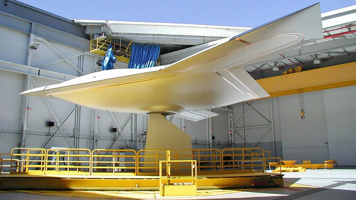
The silvery stretched pumpkin seed shape on the end of the main pylon, (and the shape on the pylon at Pit 2), is a “polecap”. The “Star”, a company newspaper published by the Lockheed Martin Skunkworks, in the June 21, 1996 issue, ran a photo of the new pylon and polecap on its front page (shown below). The polecap is used during calibration of the main pylon. The shape of the pylon is so stealthy, that only the very tip of the pylon ends up being a significant source of signal return. To minimize this, a precisely shaped polecap is placed on the tip of the pylon to eliminate any radar returns from this spot. Then, once the very small return from the pylon is accurately determined and the system calibrated, the polecap is removed and a model put in its place. Perhaps surprisingly, the polecap was fabricated for Lockheed by a boat-building firm, Goetz Boats in Bristol, Rhode Island. It consists of aluminum honeycomb and carbon fiber, and the band along the outside edge is made of Kevlar, and the whole thing coated with RAM. After fabrication, it was shipped across country on a flatbed truck, looking to the world like the hull of a racing yacht.”
RQ-3 Dark Star and F-22 being tested at Helendale. , Lockheed
So a ton of engineering went into what appears as a fairly sparse but peculiar facility from a distance, and from above. The Pentagon contracted their own iteration of the design around the same time as Helendale was receiving its upgrades in 1985. Known as the Radar Advanced Measurements (RAM) and Radar Target Scatter (RASCAT) facility, it’s part of the National Radar Cross Section Test Facility (NRCSTF). The remote installation is located near Holloman AFB, among the White Sands Missile Range. It is the most advanced RCS range in the government’s portfolio and features a very similar underground staging facility as the one built at Helendale.
The main NRCSTF, located roughly 35 miles from the RAS/RASCAT facility, is where Northrop and Lockheed had their “pole off” during the XST competition , which ended in Lockheed winning the contract that would eventually give birth to Have Blue and the F-117 Nighthawk. During this early test of stealth design, the radar operator thought Lockheed’s “Hopeless Diamond” model fell off the pole until a bird landed on it and a return suddenly showed up on his scope.
Northrop’s XST stealth tactical aircraft contender on the pole during the competition which saw it face off against Lockheed’s “Hopeless Diamond” design., Public Domain
You can get an unprecedented look side Lockheed’s Helendale RCS range in this video, which includes some very interesting comments from one of the top engineers that runs the site on what has been tested there, and what is possibly flying today under the cloak of deep classification:
With the big changes that have come to rapid prototyping and additive manufacturing, one would have to imagine that building new models and shapes to test at RCS ranges like Helendale has become a faster, cheaper affair for major aerospace companies like Lockheed Martin. It is known that the Skunk Works in particular has taken a very aggressive approach to these capabilities, along with efficiently building large composite structures , dating back to the early 2000s . And considering how potential enemies’ radar and integrated air defense system technology is rapidly evolving, being able to better validate and tune new designs to be as stealthy as possible has become more important than ever.
Whereas stealth aircraft like the F-117 , and even the F-35 to a large degree, are optimized for low observability in certain radar bands and from certain aspects, next generation stealth aircraft designs, l ike the B-21 Raider , will feature broadband low observability , which aims to counter a wide number of frequency bands from all aspects. Even morphing aircraft structures will work to reduce an aircraft’s detectability by radar in the future. As such, testers at Helendale and other RCS facilities will be more challenged than ever to provide the critical data needed to keep stealth a relevant technology in the coming decades and to validate much more dynamic aircraft designs against multiple radar bandwidths.
But regardless of its capabilities or its critical mission, when it comes to just visuals alone, there are few facilities in the world that look as Hollywood ready as the Helendale RCS range.
Contact the author: Tyler@thedrive.com
Comments couldn’t be loaded. Please refresh the page.
更新于美国东部时间2019年4月1日晚上8:51
即使美国的国防预算规模庞大得令人难以置信,大多数人看到遍布美国各地、用于测试和研发新型军事技术和武器的众多精密设施时,仍然会感到震惊。这些设施包罗万象,从用于测试导弹导引头的巨型录音棚式建筑,到用于测试新型潜艇技术的湖泊,应有尽有。此外,还包括许多室外雷达截面测量设施,在航空航天和国防领域通常被称为“RCS测试靶场”。
从佛罗里达州棕榈滩到俄勒冈州博德曼,这些靶场经常被误认为是秘密机场,或者与地下基地甚至外星科技等阴谋论联系在一起。但它们的真正作用是利用不同的雷达带宽,从不同角度仔细评估飞机设计的雷达特征。
雷达特征测试场的历史可以追溯到低可探测性飞机设计的开端,但随着隐形革命在 20 世纪 70 年代末和 80 年代初的最终兴起,它们的科技水平比之前的测试场要先进得多。
这些测试设施的任务本身就要求使用一块开阔的场地,场地内需有一条平坦的线性区域,且与各种雷达发射器呈直线排列。测试人员会使用一根或多根杆子(通常设计成锐角或采用雷达透明材料,例如泡沫)将飞机模型高高吊起进行测试。显然,安全是许多此类设施面临的主要问题,因为测试意味着将可能非常敏感的飞机设计和外形送上高空。因此,这些设施通常位于非常偏僻和/或预先设防的区域,并配备了复杂的安全措施和清晰的边界标识。
洛克希德·马丁公司臭鼬工厂的Helendale RCS靶场,谷歌地球
RCS测试设施通常还配备滑动式掩体,用于在不进行测试时隐藏测试对象;此外还有大型机库式建筑用于存放测试对象;更不用说在设施的另一端,与测试塔架相对的位置,至少会有一组大型天线阵列。最后,一些设施还设有地下区域,其功能与移动式掩体类似,但更加实用。所有这些设施组合在一起,使得RCS测试设施看起来更像是电影《第三类接触》的布景,而不是对模型飞机进行雷达测量的地方。
在所有雷达截面测试设施中(除了51区的DYCOMS系统和NT-43A RAT飞行器之外),洛克希德·马丁公司的海伦代尔雷达截面测量设施是最精密复杂的设施之一。该设施地理位置优越,位于莫哈韦沙漠,距离洛克希德公司位于加利福尼亚州帕姆代尔42号工厂的臭鼬工厂总部仅45英里,占地约10平方英里,原址是二战时期的海伦代尔机场。事实上,该机场的一条旧跑道至今仍在使用,供小型飞机起降,例如洛克希德公司运营的PC-12飞机,这些飞机负责将人员运送到美国西南部各地的秘密地点,并且该跑道还配备了夜间照明设施。但需要明确的是,这条跑道并不对外开放。
现代化的海伦代尔靶场设施一期工程建于 20 世纪 80 年代初——正值隐形技术蓬勃发展之际。那时,臭鼬工厂的 F-117“夜鹰”战斗机已经以高度机密的方式投入使用,从内华达沙漠深处的托诺帕试验场机场和 51 区起飞作战。
1985年,该设施进行了一次重大升级,从原本标准的双坑布局(最远的坑距离主天线阵列5500英尺)扩展到三坑布局,总长度约为8200英尺。第三个也是最远的坑位于最远端,由一个巨大的、类似掩体的混凝土结构构成,其中包括一根大型可伸缩杆和一个用于对测试件进行轻度改装、安装和拆卸的地下平台。这个地下机库状结构被称为“上层舱室”,它本身就是一个现代奇迹,拥有可伸缩的顶棚和可伸缩的、非常隐蔽的测试杆,测试杆可以升至坑上方高处,也可以缩回上层舱室深处。
这是洛克希德·海伦代尔RCS靶场“上层舱室”内可伸缩塔架顶部的杆帽的航拍图像。(图片来源:Otherhand.org)
在设施的另一端,靠近主阵列的位置,分布着一系列机库、辅助和控制建筑。高达70英尺的大型碟形阵列位于一块完美平坦的混凝土板底部,这块混凝土板延伸约7500英尺,直至地下坑。表面极其光滑,设计上完全消除了地球的自然曲率。设施的各个主雷达阵列集中布置在一起,每个阵列都连接到一个液压升降机,可以上下移动。其他雷达阵列可以放置在靶场更远处的杆子附近,并安装在轨道上,以便于移动。以下是一些该设施的精彩航拍照片。
根据网站 Otherhand.org 的描述(该网站还有一些很棒的装置注释图片),沿平面间隔分布的三个坑是这样描述的:
从天线阵列向下游移动 1400 英尺,我们来到 1 号天线坑。在此位置,测试对象可以放置在四种不同的支架上。支撑结构可以是 14 英尺长的金属或复合材料塔架、泡沫柱或充气柱。安装在 1 号坑的目标长度可达 14 英尺,重量可达 1600 磅。目标使用起重机或叉车放置在支架上。在 1 号坑的正上游,从靶场地面可以看到一个长长的白色金属盖。盖板下方是一个铰链式校准塔架。在 1 号坑测试模型之前,校准塔架会展开,上面安装一个已知形状的物体。操作中心的技师可以根据已知形状调整和校准他们的设备。之后,校准塔架会缩回,并测量实际模型。接下来,我们距离天线阵列 5000 英尺,来到 1 号坑。 2. 这个深80英尺的坑地面上覆盖着白色铰链门,坑内设有一个由液压缸伸缩的塔架。在这些门的正下方,塔架缩回的上方,是一个小型工作室,可以将长度达50英尺、重量达6000磅的模型安装到塔架上。紧邻2号坑且位于其上游的是另一个小得多的坑,坑内设有一个安装在铰链塔架上的校准模型。它的功能与1号坑的校准坑相同。这几乎就是海伦代尔设施一期工程的全部内容。但在1985年,扩建工程启动,并安装了许多重要的设备。在距离主天线阵列5300英尺处,增加了一个直径60英尺的大型移动天线,该天线安装在履带式运输车上。不使用时,运输车会将大型碟形天线横向移动到靶场的西侧。这个巨大的天线需要专门建造路基和桥梁。位于防洪渠上方。这根名为 MOBATS 的天线用于低频高功率射频测量。这根移动式爬行天线似乎是为了替代原计划在 5400 英尺高度建造但从未实施的天线坑。在 7300 英尺高度,我们会看到靶场地面上一个很长的白色金属盖板。盖板下方是另一个校准坑(50 号区域),它是靶场中最大的校准坑,长达 130 英尺。与其他校准塔一样,它的升起方法也很简单。塔的一端仅用铰链连接,打开盖板后,它便从井内的水平位置升至近乎垂直的位置。同样,它的目的是将已知形状和尺寸的物体放入雷达波束中,以便在进行实际模型测试之前校准接收设备。该设施的亮点位于 7500 英尺高度。这个位于靶场远端凹陷处的奇特结构被称为“上层室”。 (或施工期间的30号区域)。虽然它看起来像是用实心混凝土建造的,但实际上是由混凝土砌块构成的。在建筑物垂直面的一侧,40英尺高的墙面上有一个大型侧滑式机库门。模型就是通过这扇门被送入上层舱室的。仔细观察上层舱室的屋顶,会发现一个边长80英尺的方形盖板,沿对角线有一条缝隙。这个盖板可以从两侧收缩,沿对角线分开,露出一个通往下方上层舱室的80英尺见方的开口。关闭时,气囊装置会密封对角线接缝。令人惊讶的是,上层舱室内部的可用面积比从外部看起来要小。实际的平坦地面面积只有大约130英尺乘110英尺,约14,000平方英尺。上层舱室周围大部分看似被混凝土覆盖的区域实际上是覆盖的斜坡。在建造时,这部分区域没有被使用,而是保持覆盖状态。但光秃秃的山坡。”
从天线阵列向下游移动 1400 英尺,我们来到 1 号天线坑。在这个位置,测试目标可以放置在四种不同的支架上。支撑结构可以是 14 英尺长的金属或复合材料塔架、泡沫柱或充气柱。安装在 1 号天线坑的目标长度可达 14 英尺,重量可达 1600 磅。目标在此处使用起重机或叉车放置在支架上。
在1号靶场正上方,靶场地面上可以看到一个长长的白色金属盖板。盖板下方是一个铰链式校准塔。在1号靶场进行模型测试之前,校准塔会展开,并在其上安装一个已知形状的物体。操作中心的技师可以根据这个已知形状调整和校准他们的设备。之后,校准塔会缩回,并测量实际模型。
接下来,我们来到距离天线阵列 5000 英尺(约 1524 米)处,即 2 号坑。这个 80 英尺(约 24 米)深的坑口上方装有白色铰链门,坑内设有一根由液压缸伸缩的塔架。在这些门的正下方,塔架收起的上方,是一个小型工作室,可以将长度达 50 英尺(约 15 米)、重量达 6000 磅(约 2723 公斤)的模型安装到塔架上。紧邻 2 号坑且位于其上游方向的是一个小得多的坑,坑内也安装了一个安装在铰链塔架上的校准模型。它的功能与 1 号坑的校准坑相同。
这基本上就是海伦代尔设施一期工程的极限了。但到了1985年,扩建工程启动,并安装了许多重要的先进设备。
在距离主天线阵列5300英尺处,增设了一台直径60英尺的大型移动天线,该天线安装在履带式运输车上。不使用时,运输车会将这台大型碟形天线横向移动到靶场西侧。为了安装这台巨型天线,需要专门修建路基和桥梁,跨越一条防洪渠。这台名为MOBATS的天线用于低频高功率射频测量。这台移动式履带天线似乎是为了替代原计划在5400英尺处建造但最终未能实施的天线坑。
在7300英尺的高度,我们会看到靶场地面上一个很长的白色金属盖板。盖板下方是另一个校准坑(50号区域),它是靶场中最大的校准坑,长达130英尺。与其他校准塔架一样,它的升起方法也很简单。塔架仅在一端设有铰链,打开盖板后,即可将其从井内的水平位置升至近乎垂直的位置。同样,它的作用是在实际模型测试之前,将已知形状和尺寸的物体放入雷达波束中,以校准接收设备。
该设施的精华位于海拔7500英尺处。这座奇特的建筑坐落在靶场尽头的洼地中,被称为“上层舱室”(或建造期间的30号区域)。虽然它看起来像是用实心混凝土建造的,但实际上是由混凝土砌块构成的。在建筑垂直面的一侧,40英尺高的墙面上有一个大型侧滑式机库门。模型就是通过这扇门被送入上层舱室的。
仔细检查上层墓室的顶部,会发现一个边长80英尺的方形盖板,盖板沿对角线有一条缝隙。这个盖板两侧可以向内收缩,沿对角线分开,露出一个通往下方上层墓室的80英尺见方的开口。关闭时,气囊装置会密封对角线接缝。
令人惊讶的是,上层墓室内部的可用面积比从外部看起来要小。实际的平坦地面面积只有大约130英尺乘110英尺,约14000平方英尺。上层墓室周围看似被混凝土覆盖的大部分区域实际上是覆盖着混凝土的斜坡。在建造时,这部分区域并未被利用,而是保持了覆盖状态,裸露着。
测试样品放置在杆上,正被移动到暴露位置。(YouTube 截图)
该网站接着描述了上层墓室的内部空间:
上层空间主要用作工作间和操作台。这里有一台大型架空桥式起重机,用于移动和操作RCS模型。此外,还有一台柴油发电机、一个控制室、卫生间以及位于一端的小型绞车室。这里没有办公区域。上层空间的右后侧主要由筒仓及其盖子占据。筒仓,也称为35号区域,位于上层空间的正下方,占据了大部分可用空间。它是一个巨大的圆形竖井,内径33英尺,深度达上层空间下方210英尺。筒仓由钢筋混凝土建造,最小壁厚为3.5英尺。筒仓的上部壁稍厚一些。仅筒仓结构的建造就需要超过3000立方码的混凝土。这相当于大约300辆满载水泥的搅拌车的量,因此当地居民才会有“水泥车排成一排”的景象。该设施在建造过程中耗费了数英里的时间。筒仓的深度远低于邻近的莫哈韦河地下水位,因此持续抽干渗水至关重要。有传言称,筒仓的设计参考了泰坦导弹地下发射井。如果属实,那么在建造期间,苏联间谍卫星无疑对该地点表现出了极大的兴趣!筒仓内设有一个可伸缩的塔架,模型放置在塔架上,以便升入雷达波束进行测量。塔架下方是一个平衡式升降结构,由双缆绞车机构升降。除了梯子外,筒仓内还设有一部小型瑞典制造的人员升降机,方便人员前往各个楼层。测试时,模型(甚至全尺寸飞机)通过侧面的滑动门进入上层舱室,由桥式起重机升起,放置在塔架顶端。完成必要的校准后,上层舱室的顶盖打开,塔架开始上升。该塔架于1996年5月进行了升级,采用了一种新型的、更具隐蔽性的设计(洛克希德公司称之为“方背超级裙板”)。它能够将模型前后移动7英尺,或旋转360度,以便于清理上层舱室顶部的开口。塔架的移动能力也用于测试项目。当塔架完全伸展时,液压缸会将其向前倾斜至与水平面成55度角,此时舱室顶部可能会在其下方关闭。当塔架完全升起并处于正常倾斜位置时,它可以将模型或实际飞机(重量可达30,000磅,尺寸最大可达105英尺×73英尺)放置在上层舱室顶部上方约100英尺处。主塔架末端的银色拉伸南瓜籽状部件(以及2号坑塔架上的形状)是“杆帽”。《星报》是洛克希德·马丁公司出版的一份公司报纸。 1996年6月21日出版的《臭鼬工厂》杂志头版刊登了一张新型塔架和顶盖的照片(如下图所示)。顶盖用于主塔架的校准。塔架的形状非常隐蔽,只有塔架的尖端会发出明显的信号。为了最大限度地减少这种信号,在塔架尖端安装了一个形状精确的顶盖,以消除该位置的任何雷达反射。然后,一旦精确测定了塔架的微弱反射信号并完成了系统校准,顶盖就会被移除,并换上一个模型。或许令人惊讶的是,这个顶盖是由位于罗德岛州布里斯托尔的戈茨造船厂(Goetz Boats)为洛克希德公司制造的。它由铝蜂窝和碳纤维构成,外缘的带状部分由凯夫拉尔纤维制成,整个顶盖都涂有RAM涂层。制造完成后,它被装在平板卡车上运往全国各地,在世人眼中,它就像一艘赛艇的船体。
上层舱室主要用作工作间和操作台。舱内设有一台大型架空桥式起重机,用于移动和操作RCS模型。此外,舱室一端还设有柴油发电机、控制室、卫生间和一个小型绞车室。舱内没有办公区域。上层舱室的右后侧主要由筒仓及其盖子占据。
这个筒仓,也被称为35号区域,位于上层舱室地板正下方,占据了大部分可用空间。它是一个巨大的圆形竖井,内径33英尺,深达上层舱室地板以下210英尺。筒仓由钢筋混凝土建造,最小壁厚为3.5英尺。筒仓上部的墙壁略厚一些。仅筒仓主体结构就需要超过3000立方码的混凝土。这相当于大约300辆满载水泥的搅拌车的量,因此当地居民才会在建造期间看到“水泥搅拌车排起长龙”的景象。筒仓的深度远低于邻近的莫哈韦河地下水位,因此必须确保渗水能够持续排出。有传言称,筒仓的设计参考了泰坦导弹地下发射井。如果属实,那么在施工期间,苏联间谍卫星无疑对该工地表现出了浓厚的兴趣!
筒仓内设有可伸缩式塔架,模型放置在塔架上,以便升至雷达波束范围内进行测量。塔架下方是一个配重式升降结构,由双缆绞车机构升降。除了梯子外,筒仓内还设有一部小型瑞典制造的人员升降机,方便人员前往各个楼层。
测试时,模型(甚至全尺寸飞机)通过侧面的滑动门进入上层舱室,由驾驶台起重机吊起,放置在塔架顶端。完成必要的校准后,上层舱室的顶盖打开,塔架开始升起。该塔架于1996年5月进行了升级,采用了一种新型的、更具隐身性的设计(洛克希德公司称之为“方形超裙板”)。升级后的塔架能够使模型前后移动7英尺(约2.1米)或旋转360度,以便顺利通过上层舱室顶盖的开口。塔架的移动能力也用于测试程序中。
当塔架完全伸展时,液压缸会将塔架向前倾斜至与水平面成 55 度角,此时塔架下方的顶棚即可关闭。在正常倾斜位置完全升起后,塔架可以将模型或实物飞机(重量可达 30,000 磅,尺寸最大可达 105 英尺 x 73 英尺)放置在上层舱室顶棚上方约 100 英尺处。
主塔顶端(以及2号坑塔架上的形状)银色的、拉长的南瓜籽状物体是“杆帽”。洛克希德·马丁公司臭鼬工厂出版的报纸《星报》在1996年6月21日的头版刊登了新塔架和杆帽的照片(如下图所示)。杆帽用于主塔架的校准。塔架的形状非常隐蔽,只有塔尖会发出明显的信号回波。为了最大限度地减少这种回波,在塔尖安装了一个形状精确的杆帽,以消除该位置的任何雷达回波。然后,一旦精确测定了塔尖的微弱回波并校准了系统,杆帽就会被移除,并换上一个模型。或许令人惊讶的是,这个杆帽是由位于罗德岛州布里斯托尔的戈茨造船厂为洛克希德公司制造的。它由铝蜂窝和碳纤维构成,外缘饰带采用凯夫拉尔纤维,整体涂有RAM涂层。制造完成后,它被装在平板卡车上运往全国各地,在世人眼中就像一艘赛艇的船体。
RQ-3“暗星”和F-22正在海伦代尔进行测试。洛克希德公司
因此,从远处或空中俯瞰,这座看似简陋却又奇特的设施背后,凝聚了大量的工程心血。大约在1985年海伦代尔基地进行升级改造的同时,五角大楼也委托建造了他们自己的类似设计。这座名为“雷达先进测量(RAM)和雷达目标散射(RASCAT)设施”的建筑,是国家雷达截面测试设施(NRCSTF)的一部分。该远程设施位于霍洛曼空军基地附近,毗邻白沙导弹靶场。它是美国政府最先进的雷达截面测试靶场,其地下平台设施与海伦代尔基地的设施非常相似。
位于距离 RAS/RASCAT 设施约 35 英里的主 NRCSTF 基地,是诺斯罗普·格鲁曼公司和洛克希德·马丁公司在 XST 竞标期间进行“杆式测试”的地方。最终,洛克希德·马丁公司赢得了合同,这份合同最终催生了“Have Blue”隐形系统和 F-117“夜鹰”战斗机。在这次早期的隐形设计测试中,雷达操作员一度以为洛克希德公司的“绝望钻石”模型从杆子上掉了下来,直到一只鸟落在上面,雷达屏幕上才突然出现了回波信号。
在与洛克希德·马丁公司的“绝望钻石”(Hopeless Diamond)设计方案的竞争中,诺斯罗普公司的XST隐形战术飞机方案脱颖而出。(公共领域)
在这段视频中,您可以前所未有地了解洛克希德公司的 Helendale RCS 系列产品,其中包括一位负责该基地的顶级工程师对已测试产品以及目前可能在高度机密的掩护下进行测试的产品发表的一些非常有趣的评论:
随着快速原型制作和增材制造技术的飞速发展,可以想象,对于洛克希德·马丁等大型航空航天公司而言,制造用于在海伦代尔等雷达反射截面积(RCS)测试场进行测试的新模型和形状,已经变得更加快捷、经济。众所周知,臭鼬工厂尤其积极致力于提升这些能力,并高效地制造大型复合材料结构,其历史可以追溯到21世纪初。考虑到潜在敌方雷达和综合防空系统技术的快速发展,更好地验证和调整新设计以使其尽可能隐蔽,变得比以往任何时候都更加重要。
虽然像F-117这样的隐形飞机,甚至很大程度上包括F-35,都针对特定雷达频段和特定角度的低可探测性进行了优化,但下一代隐形飞机设计,例如B-21“突袭者”,将采用宽带低可探测性,旨在从各个角度对抗多种频段的雷达探测。未来,即使是可变形的飞机结构也将有助于降低飞机被雷达探测到的可能性。因此,位于海伦代尔和其他雷达散射截面(RCS)测试设施的测试人员将面临前所未有的挑战,他们需要提供关键数据,以确保隐形技术在未来几十年内保持其相关性,并验证更具动态性的飞机设计在多种雷达频段下的性能。
但无论其功能或关键任务如何,仅就视觉效果而言,世界上很少有设施能像 Helendale RCS 靶场那样看起来如此好莱坞级别。
联系作者:Tyler@thedrive.com
评论加载失败,请刷新页面。