The F-111 Aardvark’s Air Inlet Spike Was A Work Of Engineering ArtF-111“土豚”战斗机的进气尖锥是一项工程艺术杰作。
The engineering that went into feeding the jet's finicky turbofan engines with large volumes of stable air is fascinating in its own right.
新闻视频
Updated May 3, 2020 4:16 PM EDT
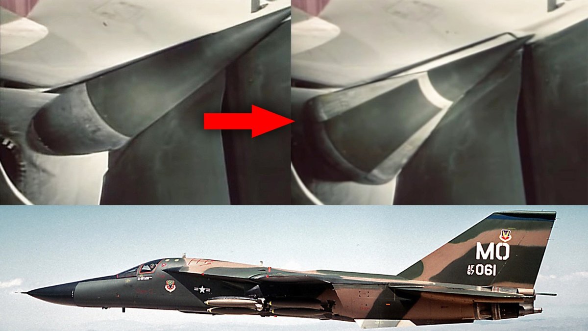
The swing-wing F-111 Aardvark had a very tumultuous genesis, but there was no doubt that it was extremely advanced for its time. It never ended up serving with the Navy, but the Air Force made good use of it for the tactical and strategic strike roles, as well as an electronic warfare platform in the form of the EF-111 Raven. The jet looked like a sharp, hot knife slicing through the air at low-level and high-speed. It certainly was fast, but this high-speed capability came in part from the result of the aircraft’s fascinating variable geometry inlet ‘spike and cone’ design that helped feed massive volumes of stable air into the jet’s troublesome twin Pratt & Whitney TF30 turbofan engines.
The F-111’s spike and cone design almost looks organic it is so beautifully engineered. The complexity of the Aardvark’s inlet configuration is well known. After its initial configuration, it went through two subsequent design iterations, named the Triple Plow I and Triple Plow II, in an attempt to overcome issues with airflow to the TF30s that were becoming notoriously finicky.
You can see the entire video from where the clip of the spike and cone transitioning was taken (at 22:17 runtime) below:
The F-111’s overall intake design works to separate the boundary air layer from the fuselage and lower wings in order to provide stable, high-volumes of air into the engines. The variable geometry spike and cone arrangement is used to keep this boundary layer air out of the intake and keep supersonic air from hitting the engine fan face. You can read all about jet inlet design, which is one of the most challenging aspects of a high-performance aircraft’s design, as well some of the relatively exotic methods engineers have devised to simplify these complex systems and to make them better suited for modern low-observable (stealthy) aircraft, in these past War Zone pieces linked here , here , and here .
In a study about the efficiency of the inlets, NASA describes an early-build F-111A’s inlet functionality as such:
The test airplane had two external compression inlets beneath the wing-fuselage junctures. These inlets were approximately quarter-round segments of axially symmetric inlets, and each provided airflow to one of the engines through separate ducts about 4.11 meters (13.5 feet) long. The inlets incorporated variable geometry to attain inlet-engine airflow matching and to adjust the amount of compression throughout the operating range. Inlet geometry together with the free-stream Mach number and airflow demand of the engines fixed the position of the compression shock system. …The two-cone air compression surface or “spike,”… devices which were used to prevent low-energy boundary-layer air from entering the inlet… … Spike translation was controlled as a function of local Mach number (ahead of the inlet) and diffuser exit Mach number. This portion of the control included position feedback. Second-cone angle was controlled by the same parameters in a loop which maintained a scheduled shock position pressure ratio. … At subsonic and low transonic flight speeds, the inlet spike was normally positioned forward and the second cone fully collapsed by the inlet controller to minimize spillage drag and compression. As the aircraft Mach number increased, the spike translated rearward and the second cone expanded according to the preset control system schedule. In this way, increased compression was obtained as the supersonic flow was decelerated by two conical shocks prior to deceleration to subsonic velocities through a normal shock near the cowl lip.
The test airplane had two external compression inlets beneath the wing-fuselage junctures. These inlets were approximately quarter-round segments of axially symmetric inlets, and each provided airflow to one of the engines through separate ducts about 4.11 meters (13.5 feet) long. The inlets incorporated variable geometry to attain inlet-engine airflow matching and to adjust the amount of compression throughout the operating range. Inlet geometry together with the free-stream Mach number and airflow demand of the engines fixed the position of the compression shock system.
…The two-cone air compression surface or “spike,”… devices which were used to prevent low-energy boundary-layer air from entering the inlet…
Spike translation was controlled as a function of local Mach number (ahead of the inlet) and diffuser exit Mach number. This portion of the control included position feedback. Second-cone angle was controlled by the same parameters in a loop which maintained a scheduled shock position pressure ratio.
At subsonic and low transonic flight speeds, the inlet spike was normally positioned forward and the second cone fully collapsed by the inlet controller to minimize spillage drag and compression. As the aircraft Mach number increased, the spike translated rearward and the second cone expanded according to the preset control system schedule. In this way, increased compression was obtained as the supersonic flow was decelerated by two conical shocks prior to deceleration to subsonic velocities through a normal shock near the cowl lip.
The revised Triple Plow I and II intakes still relied on a similar spike and cone design, but in the case of the Triple Plow II, it was enlarged significantly. Other changes to the inlet design are discussed by F-111.net in some detail:
Operational F/EF-111As, F/RF-111Cs, the first FB-111A (67-0159), and the canceled F-111Ks were fitted with Triple Plow I inlets, which featured hydraulically translated cowls. The remaining FB-111A/F-111Gs, as well as all F-111D/E/Fs were fitted with Triple Plow II inlets, which featured three ‘blow-in’ doors. This redesign increased the separation between the inlets and fuselage, removed the external splitter panel, and featured inlet spikes 18-inches longer than the Triple Plow I’s. The fuselage of Triple Plow II aircraft angled back ever so slightly at the inlets to create more room between the two structures. These aircraft also featured a small, round inlet between the engine inlet and the fuselage. Finally, the F-111D/E/F and FB-111A all had a pattern of gray, and/or fiberglass-brown panels of radar absorbing material (RAM) on the interior of their inlets. A couple of “special cases”: The second FB-111A (67-0160) was fitted with Super Plow inlets, which were similar to the Triple Plow II except that the translating cowls were replaced with two ‘blow-in’ doors instead of three. The first five F-111Bs (151xxx) were fitted with essentially Triple Plow I inlets, while the last two (152xxx) had essentially Super Plows. Refer to the Ginter Book on this subject for details. While the Triple Plow II inlet reportedly increased inlet area by ten percent, it’s unclear if that was precisely true. Measurements of the inlets suggest the TP II may be marginally larger than the TP I, but nothing like ten percent. However, the frontal area of the inlets may have increased by that much because of the shifting of the inlet farther out from the fuselage.
Operational F/EF-111As, F/RF-111Cs, the first FB-111A (67-0159), and the canceled F-111Ks were fitted with Triple Plow I inlets, which featured hydraulically translated cowls.
The remaining FB-111A/F-111Gs, as well as all F-111D/E/Fs were fitted with Triple Plow II inlets, which featured three ‘blow-in’ doors. This redesign increased the separation between the inlets and fuselage, removed the external splitter panel, and featured inlet spikes 18-inches longer than the Triple Plow I’s. The fuselage of Triple Plow II aircraft angled back ever so slightly at the inlets to create more room between the two structures. These aircraft also featured a small, round inlet between the engine inlet and the fuselage. Finally, the F-111D/E/F and FB-111A all had a pattern of gray, and/or fiberglass-brown panels of radar absorbing material (RAM) on the interior of their inlets.
A couple of “special cases”: The second FB-111A (67-0160) was fitted with Super Plow inlets, which were similar to the Triple Plow II except that the translating cowls were replaced with two ‘blow-in’ doors instead of three. The first five F-111Bs (151xxx) were fitted with essentially Triple Plow I inlets, while the last two (152xxx) had essentially Super Plows. Refer to the Ginter Book on this subject for details.
While the Triple Plow II inlet reportedly increased inlet area by ten percent, it’s unclear if that was precisely true. Measurements of the inlets suggest the TP II may be marginally larger than the TP I, but nothing like ten percent. However, the frontal area of the inlets may have increased by that much because of the shifting of the inlet farther out from the fuselage.
Aussie F-111. , USAF
While other swing-wing jets, notably the F-14 Tomcat, get most of the attention, the F-111 was truly an amazing aircraft. Most may remember it best for its precision strike, low-level penetration, and spectacular dump-and-burn capabilities , but its inlet design was definitely another of its truly fascinating features.
If you would like to read about what it was like to fly the F-111 during the Cold War, make sure to read this special feature of ours.
Contact the author: Tyler@thedrive.com
Comments couldn’t be loaded. Please refresh the page.
更新于美国东部时间2020年5月3日下午4:16
F-111“土豚”可变后掠翼战斗机的研发历程可谓一波三折,但毫无疑问,它在当时堪称极其先进。虽然它最终未能服役于海军,但空军却将其用于战术和战略打击任务,并衍生出EF-111“渡鸦”电子战平台。这架喷气式飞机宛如一把锋利的热刀,在低空高速飞行时划破空气。它的速度确实很快,而这种高速性能部分归功于其独特的“尖锥”式可变几何进气道设计,该设计能够为这架飞机那两台故障频出的普惠TF30涡扇发动机提供大量稳定的空气。
F-111的尖锥式进气道设计精妙绝伦,几乎呈现出有机形态。Aardvark的进气道结构复杂,众所周知。最初的设计之后,为了解决TF30发动机气流控制方面的问题(这些问题当时已变得非常棘手),它经历了两次后续的设计迭代,分别命名为“三重犁I”和“三重犁II”。
您可以在下方观看完整视频,其中包含尖峰和圆锥过渡的片段(视频时长 22 分 17 秒处):
F-111的整体进气道设计旨在将边界层与机身和下翼隔离开来,从而为发动机提供稳定、大流量的空气。可变几何形状的尖锥结构用于防止边界层空气进入进气道,并避免超音速空气冲击发动机风扇表面。您可以在之前的“战区”文章中阅读更多关于喷气式飞机进气道设计的内容,这是高性能飞机设计中最具挑战性的方面之一。此外,文章还介绍了一些工程师为简化这些复杂系统并使其更适合现代低可探测性(隐身)飞机而设计的相对独特的方法,链接如下:[链接在此]、[链接在此]和[链接在此]。
在一项关于进气口效率的研究中,NASA 对早期型号的 F-111A 的进气口功能进行了如下描述:
测试飞机在机翼与机身连接处下方设有两处外部压缩进气口。这些进气口近似为轴对称进气口的四分之一圆弧段,每个进气口通过约4.11米(13.5英尺)长的独立管道向其中一台发动机提供气流。进气口采用可变几何形状设计,以实现进气口与发动机气流的匹配,并在整个工作范围内调节压缩量。进气口几何形状以及自由流马赫数和发动机的气流需求共同决定了压缩激波系统的位置。……双锥空气压缩面或“尖锥”……用于防止低能量边界层空气进入进气口……尖锥的平移由局部马赫数(进气口前方)和扩散器出口马赫数控制。这部分控制包含位置反馈。第二个锥角由相同的参数在一个回路中控制,该回路维持预定的激波位置压力比。 ……在亚音速和低跨音速飞行速度下,进气尖锥通常位于前方,第二锥体由进气道控制器完全闭合,以最大限度地减少溢流阻力和压缩。随着飞机马赫数的增加,尖锥向后移动,第二锥体根据预设的控制系统程序展开。这样,超音速气流在通过发动机罩唇缘附近的正激波减速至亚音速之前,先经两个锥形激波减速,从而获得更大的压缩。
测试飞机在机翼与机身连接处下方设有两处外部压缩进气口。这些进气口呈近似四分之一圆形,轴对称,分别通过长约4.11米(13.5英尺)的独立管道为其中一台发动机提供气流。进气口采用可变几何形状设计,以实现进气口与发动机气流的匹配,并在整个工作范围内调节压缩量。进气口几何形状、自由流马赫数以及发动机的气流需求共同决定了压缩激波系统的位置。
……双锥形空气压缩面或“尖锥”……用于防止低能量边界层空气进入进气口的装置……
尖峰平移由局部马赫数(入口前)和扩散器出口马赫数控制。这部分控制包括位置反馈。第二锥角由相同的参数在一个回路中控制,该回路维持预定的激波位置压力比。
在亚音速和低跨音速飞行速度下,进气尖锥通常位于前方,第二锥体由进气道控制器完全闭合,以最大限度地减少溢流阻力和压缩。随着飞机马赫数的增加,尖锥向后移动,第二锥体根据预设的控制系统程序展开。这样,超音速气流在通过发动机罩唇缘附近的正激波减速至亚音速之前,先经两个锥形激波减速,从而获得更大的压缩。
改进后的三重犁式进气道 I 和 II 仍然采用类似的尖锥式设计,但三重犁式进气道 II 的尺寸显著增大。F-111.net 对进气道设计的其他改动进行了详细讨论:
已投入使用的F/EF-111A、F/RF-111C、首架FB-111A(67-0159)以及已取消的F-111K均配备了三重犁I型进气道,其发动机罩采用液压平移式设计。其余的FB-111A/F-111G以及所有F-111D/E/F均配备了三重犁II型进气道,其进气道设有三个“吹入式”进气门。这一改进增加了进气道与机身之间的距离,取消了外部隔板,并且进气道尖刺比三重犁I型长18英寸。三重犁II型飞机的机身在进气道处略微向后倾斜,以增加两者之间的空间。这些飞机还在发动机进气道和机身之间设置了一个小型圆形进气口。最后,F-111D/E/F 和 FB-111A 的进气道内侧都铺设了灰色和/或玻璃纤维棕色的雷达吸波材料(RAM)面板。有几个“特殊情况”:第二架 FB-111A(67-0160)配备了超级犁式进气道,其与三重犁式 II 型进气道类似,区别在于将平移式整流罩替换为两个“吹入式”进气门,而非三个。前五架 F-111B(151xxx)基本上配备了三重犁式 I 型进气道,而最后两架(152xxx)则基本上配备了超级犁式进气道。详情请参阅金特(Ginter)关于此主题的著作。虽然据报道三重犁式 II 型进气道的进气面积增加了 10%,但尚不清楚这是否属实。进气道的测量结果表明,TP II 型进气道可能比 TP I 型略大,但远没有增加 10%。然而,由于进气口向外移动,远离机身,进气口的正面面积可能因此增加了这么多。
已投入使用的 F/EF-111A、F/RF-111C、第一架 FB-111A (67-0159) 以及已取消的 F-111K 都配备了 Triple Plow I 进气口,该进气口具有液压平移式整流罩。
剩余的FB-111A/F-111G以及所有F-111D/E/F都安装了三重犁II型进气道,该进气道设有三个“吹入式”进气门。这种重新设计增加了进气道与机身之间的距离,取消了外部隔板,并且进气道尖刺比三重犁I型长18英寸。三重犁II型飞机的机身在进气道处略微向后倾斜,以在两者之间创造更大的空间。这些飞机还在发动机进气道和机身之间设置了一个小型圆形进气口。最后,F-111D/E/F和FB-111A的进气道内侧都贴有灰色和/或玻璃纤维棕色的雷达吸波材料(RAM)面板。
有几个“特殊情况”:第二架FB-111A(67-0160)配备了超级犁式进气道,其与三犁式进气道II类似,区别在于将可移动式整流罩替换为两个“吹入式”进气门,而非三个。前五架F-111B(151xxx)基本上配备了三犁式进气道I,而最后两架(152xxx)则基本上配备了超级犁式进气道。详情请参阅金特关于此主题的著作。
据报道,三重犁式进气口 II 的进气面积增加了 10%,但这一说法是否准确尚不清楚。进气口的测量结果表明,TP II 可能比 TP I 略大,但远未达到 10%。然而,进气口的迎风面积增加这么多可能是由于进气口位置向外移动,远离机身造成的。
澳大利亚的F-111战斗机,美国空军
虽然其他可变后掠翼战斗机,尤其是F-14“雄猫”,更受关注,但F-111也确实是一款令人惊叹的飞机。大多数人可能对它的精确打击、低空突防和惊人的倾泻燃烧能力印象深刻,但它的进气道设计无疑也是其另一大亮点。
如果您想了解冷战时期驾驶 F-111 战斗机的经历,请务必阅读我们的这篇专题报道。
联系作者:Tyler@thedrive.com
评论加载失败,请刷新页面。