The YF-23’s Air Inlet Design Was Its Most Exotic Feature You Never Heard OfYF-23的进气口设计是它最奇特的特点,但你可能从未听说过。
Northrop engineers used an innovative solution for dealing with an old airflow problem that is especially troublesome for stealthy designs.
Updated May 15, 2018 9:11 PM EDT
The loser to Lockheed’s YF-22 for the Advanced Tactical Fighter competition, Northrop’s YF-23, has turned into a mythical beast of sorts within military aviation circles. Not only do throngs of aficionados and analysts alike (and maybe even the Lockheed !) think it should have won that competition, but unsubstantiated rumors of a design based on it living in the clandestine realm, at least for some time, have propagated over the years. The truth is a bit more complex than just the YF-23 being the ‘perfect’ jet in retrospect—it too had advantages and disadvantages. But one of the YF-23’s most exotic design elements that has been largely overlooked was the way boundary layer air was separated from the YF-23’s fuselage before entering its air inlet and feeding its very air-thirsty next-generation turbofan engines.
Supercruise—the ability to fly for extended periods of time at supersonic speeds without the use of afterburner—was a key requirement of the ATF program. At the same time, so was low-observability (stealth). The goals of providing copious amounts of stable airflow to engines and an airframe that is hard to spot on radar can come in direct conflict with each other when it comes to designing a cutting-edge combat aircraft, and especially a super-fighter.
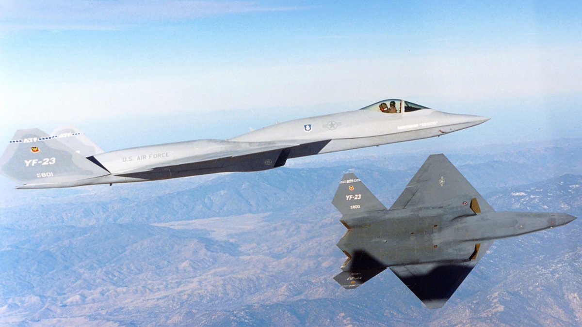
The YF-22 and YF-23—competitors in the ATF contest. , USAF
Elaborate ‘splitter plates’ and the designing of offsets that separate an air intake’s structure from the aircraft’s fuselage had been the norm for supersonic fighters prior to the ATF competition, but those concepts were not very conducive to stealth. Even a small gap between the intake and the fuselage can result in a radar cross-section increase where it matters most—from the aircraft’s forward hemisphere. Even the production F-22 design didn’t do away entirely with this feature, but Northrop’s YF-23 design did.
The YF-22 had a number of features that helped control airflow to its engines, including offset intakes and vanes that opened up above the engine inlet., USAF
Notice how the F-22A’s air intakes are still split off from the fuselage, isolating boundary layer airflow. Low observable structures and radar absorbent coatings are used to help reduce the impact of this configuration on radar cross-section., Tyler Rogoway/author
The issue has to do with boundary layer air that spreads around the aircraft’s fuselage as it flies. Boundary layer air can propagate at a different velocity and flow direction compared to the air that is offset from the aircraft’s surface and is freely gobbled up by the aircraft’s intakes. Mixing the two is far from ideal and can lead to large drops in engine efficiency, thrust instability, or worse. During certain regimes of flight, boundary layer air can become highly turbulent, largely impacting the engine’s performance or even suffocating it. The idea is to provide uniform airflow through the entire intake opening.
At supersonic speeds these issues are compounded. Other restrictions on stealth aircraft design—including the lack of variable geometry inlets, large bleed air doors, vents, and maneuvering ramps and cones used to slow down the air being ingested by the aircraft’s engines at supersonic speeds—makes providing huge volumes of stable air to high-power engines even more problematic. S-shaped air ducts not only hide highly reflective engine faces from radar waves but they also slow down the air enough during supersonic flight (up to around Mach 2) so that the engine can suck it down without shockwaves disturbing its operation. But this doesn’t solve the boundary layer issue.
So instead of creating separate intake structures with splitter gaps underneath the YF-23, Northrop installed ‘gauzing panels’ atop and ahead of where the fuselage meets the leading edge of the air intake. These panels had small holes drilled all over them and would ‘suck-up’ the boundary layer air ‘sticking to’ to the fuselage before it entered the air intake. This air was then vented out of a flush aperture and a pair of small doors on the YF-23’s upper surface. In effect, it acted like an invisible splitter plate of sorts but instead of separating the air it removed it. The system was called the Boundary Layer Control System and worked automatically.
YF-23’s gauzing plate that removed boundary layer air before entering into the intake. , Valder137/Wikicommons
Valder137/Wikicommons
As a result, the YF-23’s engine inlet design was incredibly simple. It didn’t ‘hang’ below the fuselage as a discrete structure, instead, its trapezoidal shape simply terminated into the lower fuselage itself. In this sense, it was very much a part of the fuselage. And considering there aren’t really any known major complaints about the F119 and F120 engines’ overall stability during YF-23 high-speed testing, this concept seemed to have worked well. The system may have even helped the YF-23 best the YF-22 is supercruise performance, as well.
You can clearly see these panels in photos of the YF-23, which some have wrongly attributed to an unpainted part or stealthy baffles of some sort.
Having holes drilled into splitter-plates wasn’t new. It had been done many times in the past to remove the boundary air that began to manifest itself on the plate itself before entering the engine. For instance, the Eurofighter EF2000 has this feature on its upper splitter plate that is easy to spot. The Super Hornet also uses it on the inside of its intakes. Older aircraft, like the F-4, also used perforations on their splitter plates to remove air clinging to the intake’s surface. But integrating a more refined version into the jet’s fuselage itself and eliminating the splitter plate or intake offset altogether was new.
EF2000 intake., Valder137/wikocommons
Notice the small holes in the inner-forward section of the F/A-18 Super Hornet’s intake., USN
You are probably wondering why we haven’t seen similar technology in other designs in the nearly three decades since the YF-23 took to the air. One major reason is the advent of the Diverterless Supersonic Inlet (DSI). This concept uses a forward swept intake design and a large hump-like structure blended with the fuselage of the aircraft to keep boundary layer air away from the inlet and to slow supersonic air entering the inlet to supersonic speeds.
You can check out Lockheed’s patent on their DSI technology here. , US Patent
The technology was successfully tested by Lockheed in 1996 with an F-16 acting as the test platform. The test concluded that the inlet had no adverse impact on engine operation could actually improve thrust during certain areas of the flight envelope. It could also reduce radar cross-section from the forward hemisphere by better obscuring the engine’s fan face.
F-16 DSI test aircraft from the 1990., Lockheed Martin
F-16 DSI test aircraft at Fort Worth in the 1990s., Lockheed Martin
Since then, the F-35 went on to leverage it as a key design element, as has China with their J-20 and J-31 stealth fighters aircraft and the most recent iterations of their J-10 and JF-17 fighters. In fact, there are some indications that Northrop may have been planning on integrating a DSI-like structure on their production example of the YF-23 if it had ever reached that state.
F-35’s DSI arrangement., Lockheed Martin
J-20 uses a large DSI configuration., Chinese Internet
J-10B with its DSI inlet., Chinese Internet
It isn’t clear just how the two concepts stack up to each other though. The DSI and S-shaped duct arrangement is known to limit high-speed flight to around Mach 1.6-2.0 depending on the design. This really isn’t an issue for modern fighters but it could be for an exotic design that is meant to reach higher sustained speeds, although skin heating issues begin to come into play then as well.
So there you have it, a little known exotic aspect of Northrop’s legendary YF-23 design, and another reason to sit back and wonder what could have been.
Author’s note: This is the first in a small series of articles that will explore lesser known aspects of the YF-23 in greater depth.
Contact the author: Tyler@thedrive.com
Comments couldn’t be loaded. Please refresh the page.
更新于美国东部时间2018年5月15日晚上9:11
在先进战术战斗机竞标中败给洛克希德YF-22的诺斯罗普YF-23,在军用航空界俨然已成为一个传奇。不仅众多爱好者和分析人士(或许连洛克希德公司自己也这么认为!)都认为它本应赢得那场竞标,而且多年来一直有未经证实的传闻,称基于YF-23的设计方案至少在一段时间内一直处于秘密研发状态。然而,事实远比YF-23被事后视为“完美”战机要复杂得多——它同样存在优缺点。YF-23最奇特的设计元素之一,却常常被人们忽略:它如何将边界层空气从机身分离出来,然后再让空气进入进气口,为耗气量极大的下一代涡扇发动机供气。
超音速巡航——即在不使用加力燃烧室的情况下以超音速长时间飞行——是ATF计划的关键要求。与此同时,低可探测性(隐身性能)也至关重要。在设计尖端战斗机,尤其是超级战斗机时,为发动机提供充足稳定的气流和使机身难以被雷达探测这两个目标可能会直接冲突。
YF-22 和 YF-23 是 ATF 竞赛的竞争机型。(美国空军)
在ATF竞标之前,复杂的“分离板”和将进气道结构与机身分隔开的偏置设计一直是超音速战斗机的标配,但这些设计并不利于隐身性能。即使进气道与机身之间存在很小的缝隙,也会导致雷达反射截面积在最关键的区域——飞机前半球——显著增加。即使是量产型F-22也未能完全消除这一缺陷,但诺斯罗普公司的YF-23设计则彻底解决了这个问题。
YF-22战斗机拥有多项有助于控制发动机气流的设计,包括偏置进气口和位于发动机进气口上方的导流叶片。(美国空军)
注意F-22A的进气口仍然与机身分离,从而隔离了边界层气流。低可探测性结构和雷达吸波涂层的使用有助于降低这种结构对雷达反射截面的影响。(泰勒·罗戈韦/作者)
问题在于飞机飞行时在其机身周围扩散的边界层空气。边界层空气的传播速度和流向与飞机表面以外的、被进气口自由吸入的空气不同。将两者混合远非理想状态,会导致发动机效率大幅下降、推力不稳定,甚至更糟。在某些飞行状态下,边界层空气会变得非常湍急,严重影响发动机性能,甚至使其窒息。理想的解决方案是确保整个进气口的气流均匀。
在超音速飞行时,这些问题会更加复杂。隐形飞机设计的其他限制——包括缺乏可变几何进气道、大型引气门、通风口以及用于减缓飞机发动机在超音速飞行时吸入空气速度的机动坡道和锥体——使得为大功率发动机提供大量稳定空气变得更加困难。S形进气道不仅可以遮蔽高反射率的发动机表面,使其免受雷达波的探测,而且还能在超音速飞行期间(最高可达约2马赫)充分减缓空气速度,使发动机能够吸入空气而不会受到冲击波的干扰。但这并不能解决边界层问题。
因此,诺斯罗普公司并没有在YF-23下方设计带有分离间隙的独立进气结构,而是在机身与进气口前缘连接处的上方和前方安装了“导流板”。这些导流板上布满了小孔,可以“吸走”附着在机身上的边界层空气,防止其进入进气口。然后,这些空气会通过YF-23上表面的一个齐平开口和一对小门排出。实际上,它的作用类似于一个隐形的隔板,但它不是分离空气,而是排出空气。这套系统被称为边界层控制系统,并且可以自动运行。
YF-23的导流板,用于在空气进入进气道前去除边界层空气。,Valder137/Wikicommons
Valder137/维基共享资源
因此,YF-23的发动机进气口设计极其简洁。它并非像独立结构那样“悬挂”在机身下方,而是其梯形形状直接与机身下部融为一体。从这个意义上讲,它与机身浑然一体。考虑到在YF-23高速测试期间,F119和F120发动机的整体稳定性几乎没有出现任何重大问题,这一设计理念似乎非常成功。该系统甚至可能还帮助YF-23在超音速巡航性能方面超越了YF-22。
在 YF-23 的照片中可以清楚地看到这些面板,有些人错误地将其归因于未涂漆的部件或某种隐形挡板。
在分流板上钻孔并非新鲜事。过去曾多次采用这种方法,目的是去除进入发动机前聚集在分流板上的边界气流。例如,欧洲战斗机EF2000的上分流板上就有这种设计,很容易辨认。超级大黄蜂战斗机的进气口内侧也采用了这种设计。像F-4这样的老式飞机也曾在分流板上打孔,以去除附着在进气口表面的气流。但将更精细的设计集成到喷气式飞机的机身中,并完全取消分流板或进气口偏移,这却是前所未有的。
EF2000进气口,Valder137/wikocommons
注意F/A-18超级大黄蜂战斗机进气口内侧前部的小孔。(美国海军)
你或许会好奇,自YF-23首飞近三十年来,为何我们在其他机型中没有看到类似的技术。一个主要原因是无附面层超音速进气道(DSI)的出现。这种设计采用前掠式进气道,并在机身中融入一个大型驼峰状结构,以阻挡边界层气流进入进气道,并将进入进气道的超音速气流减速至超音速。
您可以在这里查看洛克希德公司关于其DSI技术的专利:美国专利
1996年,洛克希德公司使用F-16战斗机作为测试平台,成功测试了这项技术。测试结果表明,该进气口对发动机运行没有不利影响,实际上在某些飞行包线区域还能提高推力。此外,它还能更好地遮挡发动机风扇,从而降低前半球的雷达反射截面积。
1990年代的F-16 DSI测试飞机,洛克希德·马丁公司
20世纪90年代,洛克希德·马丁公司在沃斯堡测试F-16 DSI战斗机。
此后,F-35战斗机将其作为关键设计要素加以利用,中国在其歼-20和歼-31隐形战斗机以及最新改进型的歼-10和JF-17战斗机中也采用了类似技术。事实上,有迹象表明,如果YF-23最终进入量产阶段,诺斯罗普公司可能计划在其量产机型上集成类似DSI的结构。
F-35的DSI布置,洛克希德·马丁公司
J-20采用大型DSI配置。(中国互联网)
J-10B 及其 DSI 接口,中国互联网
目前尚不清楚这两种方案究竟孰优孰劣。众所周知,DSI 和 S 形导管布局会将高速飞行速度限制在 1.6-2.0 马赫左右,具体数值取决于设计。对于现代战斗机而言,这并非什么问题,但对于旨在达到更高持续速度的特殊设计而言,则可能构成问题,尽管此时蒙皮加热问题也会随之而来。
所以,这就是诺斯罗普传奇的 YF-23 设计中一个鲜为人知的奇特方面,也是我们坐下来思考它原本可能是什么样子的另一个理由。
作者注:这是系列文章的第一篇,将更深入地探讨 YF-23 鲜为人知的方面。
联系作者:Tyler@thedrive.com
评论加载失败,请刷新页面。